| "Design, Development and Analysis of Thin Film Coated Coir Fibre for Electronic and Other Industrial Applications" |
| |
| Principal Investigator |
Co-investigator |
Co-investigator |
Dr. K. Shreekrishna kumar
Regional Director
Sciences Central Coir research Institute
Mahatma Gandhi University
Pullarikunnu Campus ,Malloossery P.O
Kottayam. |
Dr.U.S Sarma
Director
Former Joint Director
Kalavoor P.O, ALAPUZHA. |
Prof:B.Somanathan Nair
Visiting Professor, STAS
School of Technology and Applied
DTE, GOVT: of Kerala. |
|
|
The research project entitled “Design, Development and Analysis of Thin Film Coated Coir Fibre for Electronic and Industrial Applications” mainly targeted to replace commercially available non –biodegradable dielectrics used in capacitors with biodegradable organic material such as coir fibre. The processing of electronic waste in our country causes serious pollution problems because of their non biodegradable nature.Coir fibre being the hardest natural fibre, its biodegradable and eco-friendly nature makes it suitable for this specific application. Actual performances of the capacitors are highly dependent upon the dielectric used. There are many different types of capacitor based on which dielectric they use, ranging from ceramic capacitors, to electrolytic capacitors, and silver mica capacitors to various forms of plastic (e.g. polyester) capacitors. Each capacitor type has its own advantages and disadvantages and therefore the uses of the capacitor can be different. Some are better for high frequency uses, whereas others can be used for low frequency applications. Indeed it is necessary to have the right capacitor for the right use of the circuit is to work properly.Ceramic capacitors are the workhorses of capacitor world these days. Ceramic capacitors are suitable for moderately high-frequency work (into the high hundreds of megahertz range, or, with great care, into the low gigahertz range), as modern ceramic caps are fairly non-inductive compared to the other major classes of capacitors (film and electrolytic). Capacitor technologies with higher self-resonant frequencies tend to be expensive and esoteric (typically, mica or glass capacitors).Project is a search for finding a better bio degradable dielectric alternative to replace these non degradable forms (paper, plastic film, ceramic, mica etc).
|
A capacitor is composed of two conductors separated by an insulating material called a DIELECTRIC. The dielectric can be paper, plastic film, ceramic, air or mica. T A dielectric is an insulating material that when placed between the plates of a capacitor increases the capacitance by a factor called dielectric constant. The plates can be aluminium discs, aluminium foil or a thin film of metal applied to opposite sides of a solid dielectric. Coir fibre is basically an insulator. Its insulating property gives it a wide application in the field of dielectrics. Coir fibres can be processed in such a way to use as a dielectric medium. In order to make a solid dielectric Coir fibres were scrambled and pelletised.
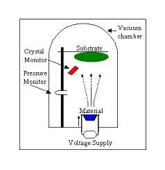
In the process of pelletisation, Coir fibres first cut into small tiny pieces and were heated up to a temperature of 1300C and 1500C for two hours. It was then powdered and pelletized in different thickness and diameter under a pressure range of 10-20 tons. Now it acts as a dielectric medium for the capacitor. These pellets are then coated with high grade silver on either side, using a vacuum coating chamber shown in the figure below. The vacuum coating unit is based on thermal evaporation and contains the essential elements typically required to obtain high vacuum. Coating is done inside a vacuum chamber where the material (silver foil), usually in a boat is heated typically to its melting point and the substrate to be deposited on is positioned facing the source a couple feet away. A high current flowing through the boat heats it up and causes evaporation. A crystal monitor is mounted close to the substrate, which provides an estimate of how much and how fast the material is being deposited. The distance between the source and the substrate is wide to prevent solid particles reaching the substrate.
The pressure inside the chamber is maintained at 4x10⁻⁵ mbar. The evaporation rate was maintained at 3Ǻ/S and the total thickness deposited on the sample was measured to be 2000Ǻ, using a quartz crystal monitor. Silver electrodes are fixed on either side of the coated pellet using silver paste. In order to add mechanical strength to the whole arrangement commercially available "araldite" was applied on both sides. This arrangement is having resemblance with the common capacitor structure available in the market. Besides as a parallel venture, we also tried an attempt to make high value resistors out of this powdered coir fibre by fiilling it in different diameter refillers and leads are fused on both sides using araldite. Thereafter measured their resistances with a high precision Keithley source meter model and got some promising results. The resistance values obtained was in higher kilo ohm range to several mega ohms but has shown some slight non reproducibility because of the lack of precision in resistor making which is understandable.
Dielectric measurements of the prepared capacitors were carried out using a Hioki 3532-50 LCR high tester. We have measured dielectric constant and dissipation factor or dielectric loss (It is the loss of power in a dielectric caused by the loss of energy in the form of heat generated by an electric field.) for different samples over a frequency range of 50 Hz to 5 MHz .we compared our different measurement parameters with published values of standard low frequency capacitors at 1 MHz and found good agreement. For instance, the case of dielectric constant parameter given as reference |
| Dielectric
Material |
Dielectric Constant
|
| Vacuum |
1 |
| Air |
1.0006 |
| Paper |
3.7 |
| Glass |
~4
– 6 |
| Polystyrene |
2.6 |
| Mica |
6.8-7.8 |
| Coir |
2.5-7 |
|
|
| |
Looking into the table we can suggest coir may be a better alternative for these low capacitance dielectric materials. The capacitors which we made come under the class of non- polarized capacitors, a type of capacitor that has no implicit polarity -- it can be connected either way in a circuit. Ceramic, mica and some electrolytic capacitors are non-polarized. These discrete capacitors of various types are available commercially with capacitances ranging from the pF range to more than a farad, and voltage ratings up to hundreds of volts.
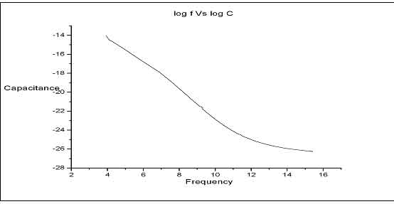
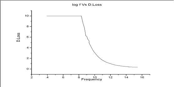
From the measurement parameter values we plotted graphs one of the samples. From the plotted graphs it can be noted that capacitance decreases with frequency which is a common nature of all commercially available capacitors in the market. Also these coir capacitors show constant Dielectric loss under low frequency range and they have got higher capacitance values during this region. So they are limited to low frequency applications due to lower dielectric losses at higher frequencies. |
 |
 |
| Despite the results produce some promising aspects, operating temperatures ranges, Maximum voltage ratings, dielectric breakdown voltages and tolerance factors are yet to be measured; then only a commercial or industrial launching is possible. |
| APPLICATIONS OF COIR FIBRE AS CAPACITOR. |
The research till date show that the capacitor developed has a well defined low frequency response and will find applications in the following areas.
- · Front end stages of Low frequency sensors and actuators especially for Bio Medical applications.
- · Low Frequency detection circuits especially in Submarine surveillance, detection and ranging.
- · Trajectory tracing circuits in underwater torpedos and Air to Sea Missiles.
- · Submarine Tracking terrestrial radars and airborne warning systems.
- · Low Frequency acoustic measuring instruments in Medical Diagnostics
|
APPLICATIONS OF COIR FIBRE AS RESISTOR. |
The sample showed extremely high resistance above 100M Ohms. This property can be effectively utilized for the following areas.
A well accepted, environmentally friendly insulator.
·
Insulation property along with adaptability to vibrations and stability in mechanically unstable foundations.
·
Will find a real application in the development of substation insulating materials especially in indoor insulation mats (In front of Electrical Panels). This will reduce the use of processed rubber and also the use of carbon black.
·
Partially Bio Degradable panels (Along with Minimum Rubber Lining) can be used for Extremely High Voltages.
·
The Coir Resistor can be used as a current limiting device in HV Testing.
·
Parallel Units will reduce the resistance where large numbers of resistors are required.
As the second part of the work coir fibers are coated with Aluminum at varying thickness. It would provide a versatile combination of physical, electrical and optical properties for a variety of demanding applications. The products would be of light weight, durable, flexible and cost competitive. It would be possible to crimp and solder or subject to textile processing with out any problem. Such materials may find use as camouflage materials that are of great importance to protect against the men and materials from enemies. Coir fiber has been designed by the nature as an insulator. Coir fiber surface can be made conducting by coating it with metals in thin films. When current is allowed to flow through these fibers, an equivalent heat will be produced to create warmth in the surroundings.
In order to make it useful in smart textile applications, one side of the coir fiber should be made conducting and the other side as insulator itself. Keeping this idea in mind, we have given a coating of silver thin film over one side of the fiber. First of all, cleaned coir fibers of about 5 cm length and 0.25 mm diameter were carefully fixed on a cellophane tape. This was to ensure that films are coated only on one side of the coir fiber. This setup was then placed on a vacuum coating unit. Pressure inside the chamber was kept at 2x10⁻⁵ Torr and source to substrate (here coir fiber) distance kept as 15cm. Thickness of the coated film has measured using a quartz crystal monitor was found to be 2000Å. A special attention was paid to maintain the coating rate at 5Å/S and pressure inside the chamber was maintained at 4x10⁻⁵ Torr during evaporation.
These samples were subjected electrical characterization. Resistances of the samples were measured using Keithley source measurement unit (model 2400). Electrodes were paced at a distance of 1cm. Resistance of the uncoated side was found as 250 MΩ, which is same as that of an uncoated fiber. Where as, the resistance on the silver coated fiber was found as 2.5Ω, having a resemblance with that of silver thin film of 2000Å thickness. Hence we could say that we are succeed in making one side of the coir fiber as conducting and other as insulator itself.
In the next stage of this work, now we are trying to study to study the heating effect of electric current through these fibers. We are passing DC current through the conducting portion of the coated fiber and trying to measure the temperature created on both sides of the fiber with the help of a PT100 temperature sensor. Work is progressing in this direction and we hope that result can be made within a time of one month.
It is also very essential to know the temperature stability of the coir fibers, in order to make them useful in smart textile applications. Hence coated and uncoated coir fibers were subjected to air annealing at different temperatures. Fibers were kept inside a furnace and annealed at temperatures 100˚C, 125˚C, 150˚C, 175˚C and 200˚C respectively. Annealing time was 30 mints. At room temperature coir fibers are golden in colour and flexible in nature. As the temperature increases colour of fiber found to change from brown to black in colour and flexibility also found to reduce. At 150˚C fibers were found to hard and beyond this temperature they are found to brittle. We are planning to carry out a micro hardness test on these samples. We hope that these studies will be useful for developing smart textiles.
So we can conclude that research progress was in the right track and the result which we got is quite trustworthy.
|
Dr. K. Shreekrishna Kumar
Principal Investigator
|
|